Go back to RESOURCES
Optimizing Fluorescence Signal Quality
Overview
Fluorescence signal quality is directly proportional to fluorescence light intensity (which is proportional to excitation light intensity, fluorescence yield of the fluorophore, and light detection efficiency) and is inversely proportional to the square-root of the sum of fluorescence light intensity and non-fluorescence light intensity (which is proportional to excitation light intensity, non-fluorescence yield, and light detection efficiency). Therefore, fluorescence signal quality will generally improve by (1) increasing excitation light intensity, (2) increasing fluorescence yield, (3) decreasing non-fluorescence light intensity, and (4) increasing light detection efficiency. Each of these topics will be discussed below, although only (1) increasing excitation light intensity will be covered extensively.
Brief fluorescence nomenclature definitions
When dealing with fluorescence in general and throughout this optimizing fluorescence signal quality procedure, several unfamiliar terms may arise. Please familiarize yourself with the following nomenclature:
- Fluorescence: the emission of a photon from a molecule (or atom) that had been energetically excited after absorbing a light photon of higher energy (shorter wavelength).
- Fluorescence Yield: the efficiency with which fluorescence light is emitted for a given wavelength of excitation light.
- Fluorescence Ratio: the ratio of fluorescence light intensities detected from two different excitation wavelengths or two different emission wavelengths.
- Numerator: the fluorescence light intensity that is used as the numerator in calculating a fluorescence ratio.
- Denominator: the fluorescence light intensity that used as the denominator in calculating a fluorescence ratio.
- Interpolated Numerator: the values for the numerator that have been approximated by interpolation from values measured before and after the time period in question.
- Interpolated Denominator: the values for the denominator that have been approximated by interpolation from values measured before and after the time period in question.
- Interleaved: the rapid and successive measurement of numerator and denominator fluorescence light intensities, thereby allowing the calculation of fluorescence ratios without interpolated values.
- Live Count: the light intensity observed by the photomultiplier tube.
How to optimize fluorescence signal quality
The following sections will address (1) increasing excitation light intensity, (2) increasing fluorescence yield, (3) decreasing non-fluorescence light intensity, and (4) increasing light detection efficiency.
Increasing Excitation Light Intensity
An object should already be placed in the microscope. This object need not be fluorescent or biological; lens paper for example may work fine. All or some of the following excitation hardware should be adjusted to maximize illumination while minimizing background. Software control of the light source is accomplished via the hardware manager (Collect>Hardware). Select the appropriate filter switcher from the hardware tree and click “Test”. This dialog allows you to select the fluorescence path. The following list should also be checked whenever there is significantly poor fluorescence signal quality:
- Light Source Power: Excitation intensity will increase with increased power. Do not set the power to be greater than the rating of the arc lamp. For example, a 75 Watt Xenon arc lamp should not be powered by more than 75 watts.
- Light Source Focus: Excitation intensity will increase with optimized focus of the arc lamp. Focusing of the light source is explained in greater detail in the HyperSwitch and uStep manuals.
- Alignment: The light path within your filter switching device can be optimized by following the procedures detailed in the appropriate manual.
- Optical Integrity: Optical filters become cloudy with use. Their replacement may improve excitation intensity.
- Liquid Light Guide Attachment to Microscope: The physical link between the liquid light guide and the microscope should be adjusted such that the light emerging from the liquid light guide is as close to the objective as possible.
- Geometry of Liquid Light Guide between Light Source and Microscope: The liquid light guide is meant to guide light along its length through multiple reflections. The direction of the light as it emerges from the liquid-light guide is somewhat dependent upon the series of the reflections, and therefore dependent upon the geometry of the guide. Of course, the user should try to optimize the direction of the light emergence so as to maximize the excitation intensity. There is no systematic strategy for optimizing the liquid light guide geometry. The user should try to maximize the live count by gently bending, straightening, and positioning the liquid-light while it is attached between the light source and the microscope. The liquid light adapter has a diaphragm which can aperture the light emerging from the light guide. The goal of this diaphragm is to prevent overfilling the objective, which can excite surfaces on the internal cavity of the objective and contribute to an increase in background at the expense of signal to noise. The diaphragm is detailed in the HyperSwitch and uStep manuals.
- Numerical Aperture of Objective: Excitation light intensity will increase with the numerical aperture of the objective. In addition, emission light intensity will increase with numerical objective.
Increasing Fluorescence Yield
Determine the excitation and/or emission wavelengths at which fluorescence is maximally induced and/or detected. This is done by referring to the fluorescence characteristics of the fluorescence dye being used. Ask the manufacturer of the fluorescence dye for these characteristics. For example, fura-2 (from Molecular Probes) not bound with calcium will fluoresce maximally when excited at 380 nm wavelength. Fura-2 bound with calcium will fluorescence maximally when excited at 340 nm wavelength. Fluorescence of fura-2 is maximally detected at 510 nm wavelength. The 340/380 nm excitation wavelength pair with a 510 nm emission wavelength detected would therefore optimize fluorescence yield for fura-2 fluorescence ratio calculations. Nevertheless, the user may wish to user other pairs. For example, the 360/380 nm excitation wavelength pair permits continuous excitation at 380 nm while fluorescence excited at 360 nm can be interpolated, because fura-2 fluorescence yield is independent of calcium at ~360 nm.
Decreasing Non-Fluorescence Light Intensity
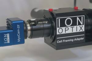
Make sure that any material that is NOT the object under investigation is NOT centered in the optical field of view of the microscope. Additionally, if there is a Cell Framing Adapter (CFA) attached to the photomultiplier tube, then adjust the field of the CFA to minimally permit passage of light from any material that is NOT the object.
Make sure that no extraneous light near the emission wavelength is entering the objective. Use a wavelength light greater than the dichroic mirror’s reflection specification (>~585 nm) for visualization. Typically our systems include an RG665 filter mounted in the condenser arm of the microscope. Make sure that the filter is being used. Additionally, block or turn off any room lights that may enter the objective. The computer monitor may also contribute the light collected by the PMT. Orient the monitor away from the stage. Dim the monitor using the monitor’s brightness and contrast controls.
Increasing Light Detection Efficiency
Make sure that the appropriate emission light path passes directly to the PMT.
The microscope prism should be positioned so that 80 or 100% of the emission light is reflected to the side port or trinocular head of the microscope, depending on where the PMT is mounted. Consult your microscope manufacturer’s documentation.
The appropriate excitation/ emission dichroic mirror should be used as well. The ex/ em dichroic is mounted in a cube and placed in your microscope’s filter turret or slider. It reflects the illumination from the arc lamp light source and transmits the emission from the fluorophore and the brightfield illumination used to visualize the cell. This will depend on the fluorophore being used. For Fura-2 fluorescence, the appropriate dichroic is a 400DCLP.
Make sure that the PMT housing is light tight, i.e., only light from the microscope
should register live counts.
If there is a high live count when light is not diverted to the PMT and room lights are low, then the housing may need to be reassembled to guarantee that it is light tight. The PMT live counts can be checked by selecting the PMT in the hardware manager and clicking “Test”.
Make sure that the PMT is not saturated with the fluorescence signal.
A common issue that arises when acquiring fluorescence is saturation of the PMT. Older systems use external accelerating voltages. We recommend that the PMT be charged at –700 V. Increasing the voltage difference will improve the efficiency of photon counting. However, a voltage difference that is too high will be so sensitive as to decrease the discrimination of high photon counts.
Newer systems using Hammamatsu H7360-02 or -03 PMTs utilize on-board amplifier/ discriminators, meaning that the accelerating HV is preset at the factory. The PMT will respond linearly when counts are below 6000. Above 6000, the PMT will not behave in a linear fashion and will begin to saturate. If the PMT sees additional light after saturation, it will output decreasing counts until it settles on a live count of “1”. The PMT’s lifetime is a function of the total current it passes. Saturating the PMT will reduce its performance and hasten its demise. The best strategy for optimizing the amount of light that reaches the PMT is to reduce the intensity of illumination through the use of a neutral density (ND) filter. ND filters attenuate light indiscriminately. In other words, there is no spectral filtering. Reducing the amount of fluorescence excitation will result is a corresponding reduction in emission. IonOptix systems come with a suite of ND filters: ND 0.2 through 1.3, which translates to light attenuation of ~33 to 95%. Using ND filters accomplishes three things: (1) reduces excessive emission, (2) minimizes photobleaching of the fluorophore, and (3) minimizes phototoxicity from excessive illumination.


